
U Type Evaporator
U Type Evaporator

Flooded Evaporator
Flooded Evaporator

Oil Cooler
Oil Cooler Heat Exchanger


Condenser
Condenser Heat Exchangers
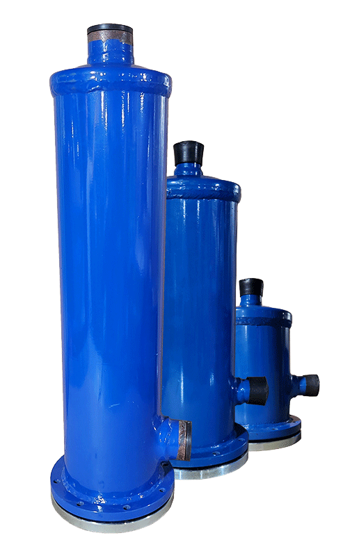
Filter Driers
Filter driers

A shell and tube heat exchanger is a type of heat exchanger widely used in various industries, including HVAC and oil and gas. As the name suggests, it consists of a large cylindrical vessel (shell) under pressure and a bundle of tubes inside. Typically, a fluid flows inside the tubes, while a hot vapor flows over the tubes and inside the shell (or vice versa). Due to the large number of tubes and the high contact surface area they create, the heat from the vapor is transferred to the fluid inside the tubes, causing the fluid to boil.
The colder fluid gains thermal energy from the hot fluid and increases in temperature, while the hotter fluid loses heat and cools down. This exchange can be described based on the fundamental principles of heat transfer, namely conduction and convection. Ideally, in a heat exchanger without energy loss, the amount of heat lost by the hot fluid is equal to the amount of heat gained by the cold fluid, and it can be calculated for each fluid using the following basic equation:
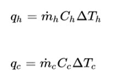
QC and QH represent the heat exchanged by the cold and hot fluids, respectively
MC and MH represent the mass flow rate of the cold and hot fluids, respectively
DT represents the temperature difference between the inlet and outlet of the cold and hot fluids
On the other hand, the relationship between the amount of heat exchanged and the contact surface area of the two fluids is defined as follows:
![]()
The amount of heat exchanged is directly related to the amount of heat transfer surface area between the two fluids. Therefore, by increasing the contact surface area between the two fluids, the efficiency of the exchanger can be increased. However, this is often met with design and operational constraints.
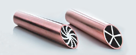
One method to increase the surface area is to create grooves on the tube surface.

The convective heat transfer coefficient, which is difficult to calculate for heat exchangers due to the continuously changing temperature along the exchanger and turbulent flows. To calculate this parameter, empirical correlations or dimensionless numbers like the Nusselt number are typically used.
Turbulent flow significantly increases the heat transfer coefficient. However, this turbulence also complicates the solution of the Navier-Stokes equations governing fluid flow. Additionally, this turbulent flow occurs inside the tubes,
further complicating the solution of the equations due to the development of the flow and the formation of a boundary layer.
The symbol DTM is used in this equation because the temperature variation along the exchanger does not follow a linear rate and is highly complex. If the exact inlet and outlet temperatures of both fluids are known, the logarithmic mean temperature difference can be used, which is defined as follows:
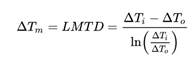
Moreover, if complete information about the inlet and outlet temperatures is not available, another method called the NTU method can be used, which only requires the inlet temperatures to the exchanger.
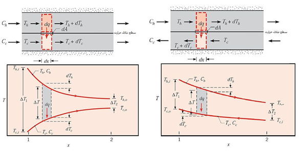
In heat exchangers, the flow paths of the hot and cold fluids can generally be arranged in two ways. In the first case, both fluids enter the exchanger from the same region and flow parallel to each other along the length of the exchanger, exchanging heat, and exiting from the other region simultaneously. This type of exchanger is known as a parallel flow exchanger. In contrast, there are counterflow exchangers where the hot and cold fluids enter from opposite ends so that at the exit point of the cold fluid, the hot fluid enters and vice versa.

Heat exchangers can be designed based on various parameters such as shape, application, and installation location. As a result, they can be categorized into different groups based on these features. The diagrams below show the classification of heat exchanger types based on the flow arrangement inside the exchanger, the overall structure of the exchanger, and the position of the shell and tube exchanger in each category.
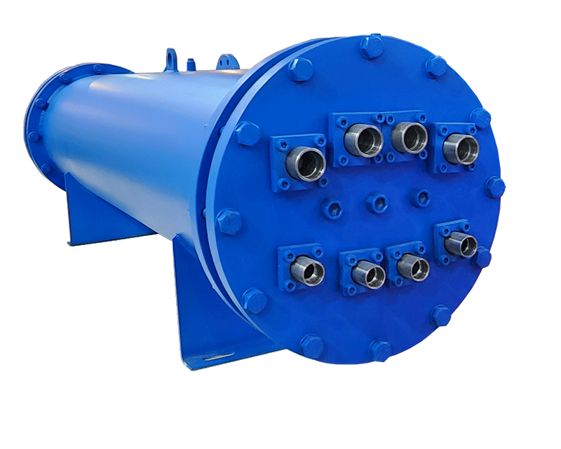
In shell and tube heat exchangers, a number or bundle of metal tubes are placed inside a larger pipe (shell). The tubes are collected from one or both ends of the shell by a perforated round plate, which acts as a header or collector for the fluid inside the tubes, also called a tube sheet.
If the tube shape is U-shaped, both ends of the tubes are located on one side of the shell and a single collector plate is used. If they are straight, the inlet is considered from one side of the shell and the outlet from the other end.
Asa Mobadle Caspian Company produces shell and tube heat exchangers of the fixed head and U-type, which are used for various purposes such as condensers, evaporators, and coolers or heaters for various fluids.