
U Type Evaporator
U Type Evaporator

Flooded Evaporator
Flooded Evaporator

Oil Cooler
Oil Cooler Heat Exchanger


Condenser
Condenser Heat Exchangers
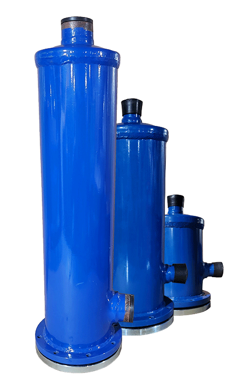
Filter Driers
Filter driers

Shell and tube heat exchangers are among the most widely used heat exchangers in industry. As their name suggests, these heat exchangers consist of a shell and a number of tubes located inside it. The basic principle of a heat exchanger is that two hot and cold fluids can exchange heat without coming into contact or mixing with each other. In a shell and tube heat exchanger, the hot fluid flows inside the shell and over the tubes, while the cold fluid flows inside the tubes, so that they exchange heat without coming into contact with each other.”
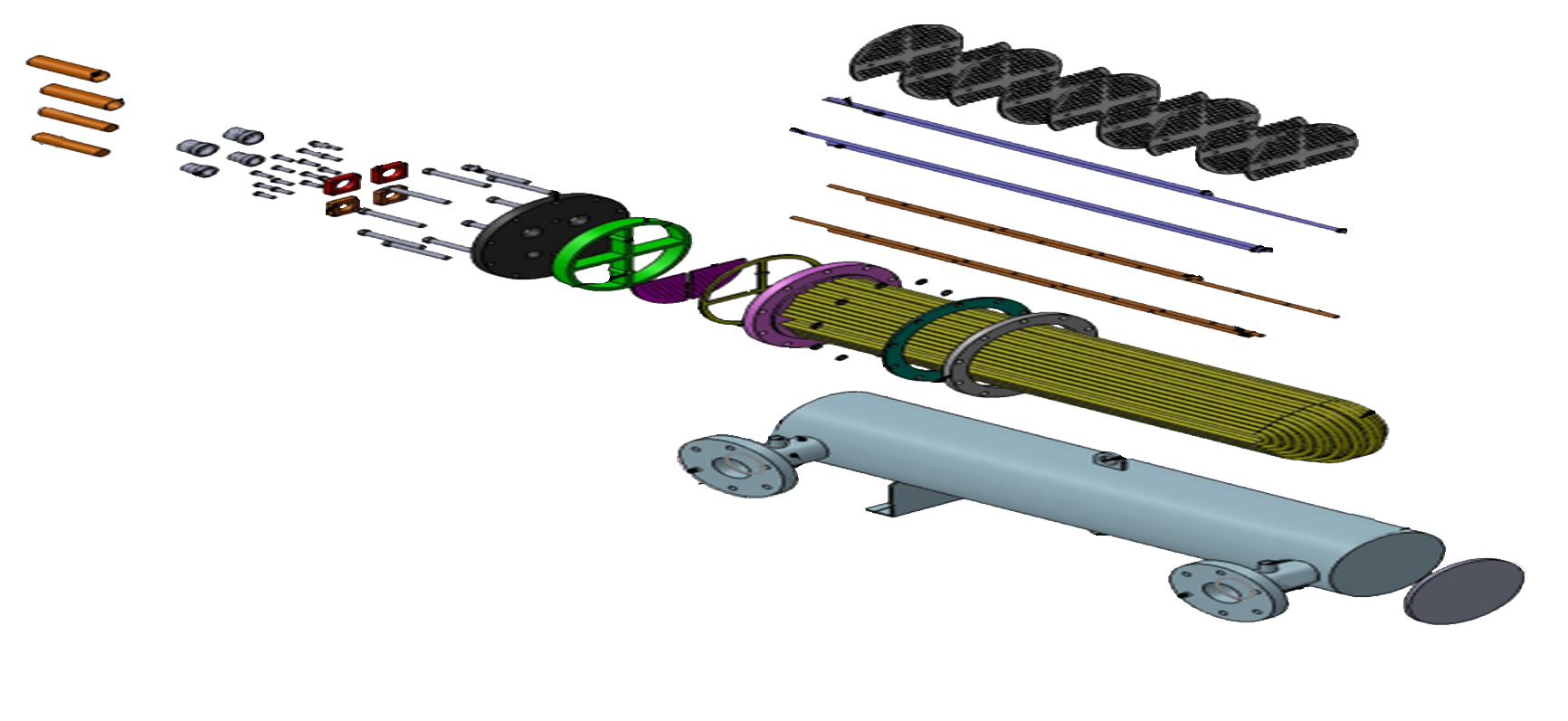
The diagram illustrates the design of U-tube heat exchangers, explaining the origin of their name. The tube bundle is composed of continuous tubes bent into a “U” shape and secured to the shell using a tube sheet (shown at the top). The cooling fluid flows through the U-shaped tubes from the top half of the inlet, then exits from the bottom half. This bend allows for thermal expansion of the fluids without requiring any expansion in the joints, as the bent portion floats freely in the shell, providing space for expansion/contraction. These exchangers perform exceptionally well when there are significant temperature differences and expansion is expected. The structure of these exchangers can also be designed with multiple passes and multiple passes.
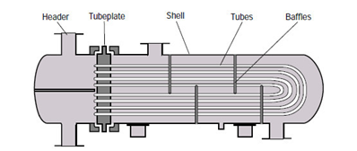
The ends of all tubes are connected to the slope tube, and in fact, its function is to restrain and seal the tubes with respect to each other.
The material of the tube sheet is also related to the fluid, pressure, temperature, properties, and corrosiveness, which is mainly made of ST52 or ST37 carbon steel in air conditioning applications.
The thickness of the tube sheet is also determined based on the tube diameter, the number of tubes, and the corresponding pressures inside and outside the shell based on various standards, including TEMA and API 660.
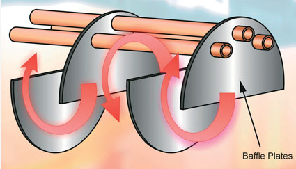
Inside the shell, plates called baffles are installed to act as fluid flow directing plates, creating turbulent flow in the fluid flowing inside the shell and maximizing heat transfer efficiency.
In a shell and tube heat exchanger with baffles (flow directing plates), the flow of fluid towards the shell is directed crosswise to the tubes between two adjacent baffles. The material of the baffles used varies depending on the type of fluid, corrosion, temperature, and pressure, but in air conditioning applications, PTFE with a thickness of 5 to 10 mm is commonly used.
The material and thickness of the baffles depend on various factors. The type of fluid or medium inside the shell, coefficients and temperature differences, the corrosiveness of the fluid, and more are factors that influence the type and thickness of the baffles.
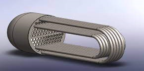
Given that one side of U-type heat exchangers is formed in a U-shape, and the expansion process between the tube and tube sheet occurs only on one side, the likelihood of cathodic corrosion and leakage from the tube sheet hole is significantly lower compared to other types of heat exchangers. Additionally, lower manufacturing costs and smaller dimensions contribute to the advantages of these exchangers.
In recent years, there has been a considerable surge in the adoption of this type of heat exchanger in the air conditioning industry. The reasons for this trend are outlined below.
Traditionally, manufacturers of mini-chillers worldwide have utilized all-stainless-steel plate heat exchangers for heat transfer. However, the drawbacks of these exchangers in regions like the Middle East and their high sensitivity—a subject worthy of further study—have prompted manufacturers to favor U-type exchangers.
These exchangers are well-suited for mini-chillers and residential or light commercial applications due to their compact size.
The manufacturing cost of these exchangers is highly competitive and, in many cases, significantly lower compared to plate heat exchangers.
Another advantage of these exchangers is the ability to repair, refurbish, and replace bundles.
It is important to note that, in recent years, due to the lack of attention to importing diverse HVAC products from the European Union, China, and Arab countries, the heat exchangers found in these products have predominantly been of the U-type, using either 3/8-inch or, in many cases, 7-millimeter tubes. Consequently, the importance of repairing and refurbishing these products further supports the use and increasing prevalence of this type of heat exchanger in the market.
AsaMobadel Caspian Company, by employing the latest design and simulation software, has introduced this type of heat exchanger as the first domestic manufacturer on a large scale. In 2021, the company successfully exported one hundred units of this exchanger to Turkey.
The production range of this product is designed for R22, R134A, R407C, and R410 refrigerants, with capacities ranging from 15 to 700 kilowatts, and is available to our valued customers.
Technical Specifications of Shell and Tube Heat Exchangers:
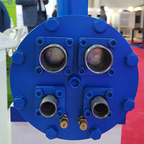
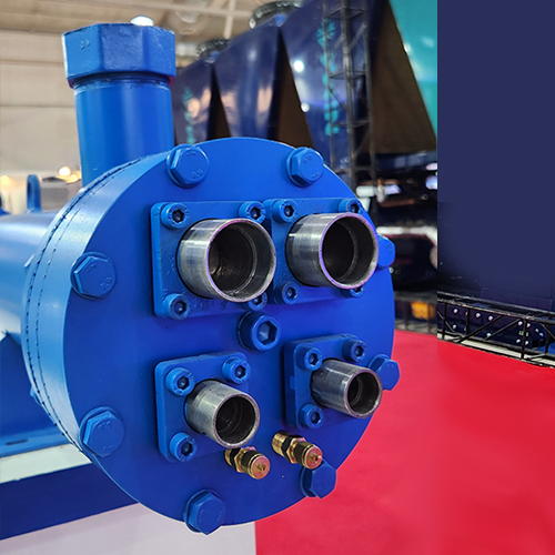
Installation of a half coupling on the exchanger for draining the fluid inside the shell and the fluid inside the tubes, as well as venting the exchanger.
Precise welding of the outer shell.
Seamless tubes are used in the coil construction.
Welding with MTIG and MAG/MIG equipment.
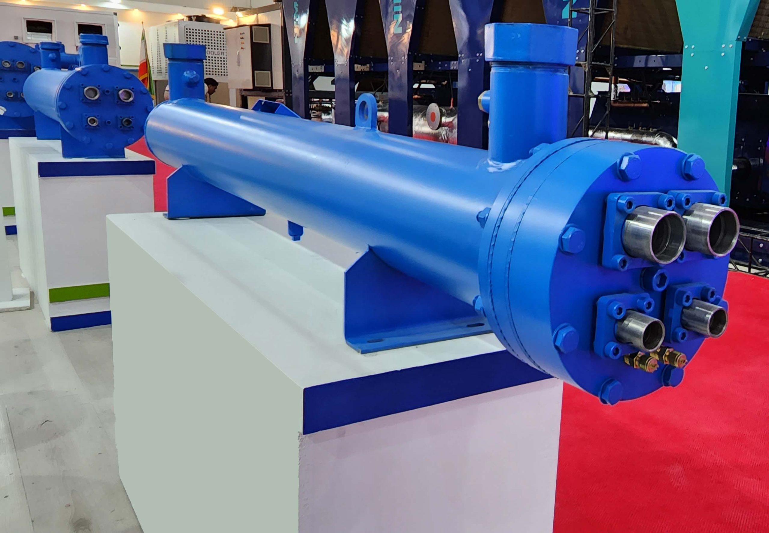
Construction of the exchanger with a very strong body and completely sealed with anti-rust internal and external surfaces and insulation of its shell with 19 mm thick foam.
Rolling and welding of tubes to the tube sheet in accordance with ASME and TEMA standards.
Design of exchangers with easy assembly and disassembly of parts for servicing and maintenance.
Design of the exchanger based on technical information and requirements provided by the customer and in the best and most suitable way in terms of design and price.
Body made of stainless steel, carbon steel, or brass, and internal tubes made of copper, brass, stainless steel, or carbon steel (depending on the type of fluid and corrosion of the fluid flowing through it).
To maximize efficiency, the heat transfer surface between the two fluids (which are the tubes) must be increased as much as possible. Therefore, a large number of tubes made of copper, steel, etc., are used. Most shell-and-tube heat exchangers are designed with 1, 2, or 4 passes. The number of passes refers to the number of return paths that the fluid takes from inside the tubes towards the outlet. For example, in a single-pass design, the fluid enters the tubes from one side and exits directly from the other side. In a two-pass design, after entering the tubes and reaching the end, the fluid changes direction by 180 degrees and exits from the same inlet side.
Applications of shell and tube heat exchangers in various industries
Types of Shell and Tube Heat Exchangers Based on Head Design
Fixed Head: In this type, the tube bundle is fixed to the tube sheet, which is attached to the shell. This design is simple but limits the thermal expansion of the tubes.
Floating Head: In this type, one end of the tube bundle is fixed to the tube sheet, while the other end is attached to a floating head cover. This design allows for thermal expansion of the tubes.
U-tube heat exchangers can be designed with either fixed or floating heads due to their 180-degree bent tube configuration. At Amka, most of our U-tube exchangers are of the floating head type, allowing for easy removal of the tube bundle by simply loosening the inlet cover bolts. This facilitates inspection, leak testing, cleaning, and re-bundling.
Lower cost: U-tube exchangers typically have the lowest cost among all types as they require only one tube sheet. Versatility: They can accommodate an even number of tube passes without thermal expansion limitations.
Wide applications: Commonly used for cooling hydraulic oil in hydraulic systems and heating water in indoor and outdoor pools. A hydraulic oil shell and tube exchanger is also called a water-oil heat exchanger.
Cleaning difficulty: The bent portion of the tubes can be difficult to clean.
Weakened tube walls: The bent portion of the tubes may have weakened walls, increasing the risk of failure. Higher cost: Generally, these exchangers have a higher manufacturing cost.
Therefore, U-tube exchangers are often used in lower capacity applications.
