
U Type Evaporator
U Type Evaporator

Flooded Evaporator
Flooded Evaporator

Oil Cooler
Oil Cooler Heat Exchanger


Condenser
Condenser Heat Exchangers
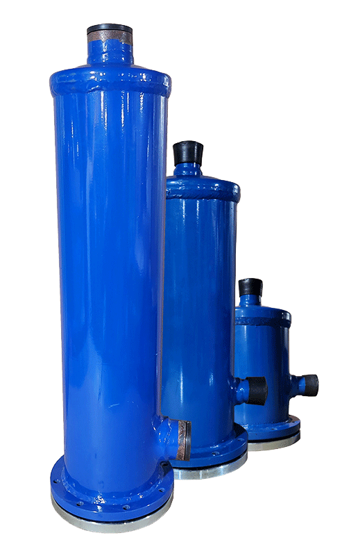
Filter Driers
Filter driers
The need for precise computational, theoretical, and academic design of heat exchangers has led to the development of various references, codes, standards, and even mathematical theories for the design and construction of heat exchangers. For more information, you can refer to the latest scientific articles and achievements of global experts in the download section.
The presence of two-phase flow, oil-contaminated fluid, and the use of multi-component refrigerants inside the tubes, along with the lack of a unified calculation method, has made the design of shell and tube heat exchangers specifically for air conditioning systems one of the most specialized and knowledge-based areas in this field.

Moreover, the existence of refrigeration compressors and the importance of oil return, pressure drop, and flow rate emphasize that the design and construction of shell and tube heat exchangers for air conditioning systems is a completely specialized, separate, and distinct field from the general design of liquid-gas heat exchangers.
Therefore, various commercial software and coding are available and used by Asamobadel Caspian Company for calculating shell and tube heat exchangers.
If the design of the heat exchanger is entrusted to Asamobadel Caspian Company:
The capacity design will be carried out according to the ARI 550/590-2015 standard, and changes in input conditions can be made specifically upon customer request.
The design and construction of shell and tube heat exchangers at AMKA will be entirely based on the TEMA Standard, ninth edition, unless the customer’s request contradicts the standard or specific specifications such as drawings or codes are mentioned in the proforma invoice.


Capacity design and calculations of heat exchangers are performed using software :
Capacity design and calculations of heat exchangers are performed using software with EUROVENT certification, some of which are listed below:
ASME Section VIII Hydrostatic Test
Hydrostatic testing based on the ASME Section VIII standard is conducted at 1.5 times the operating pressure of the heat exchanger for a duration of 30 minutes, depending on the type of refrigerant.
For evaporators, the shell is tested at 250 PSI.
For condensers, the pressure varies from 300 to 900 PSI depending on the type of gas.


Copper tubes used in condensers have a diameter of 3/4 inch, are grooved, and have various standards and FPI (fins per inch) values. Their thickness, ranging from 1 to 1.43 mm, depends on customer requirements and design specifications.
Copper tubes in evaporators have diameters of 7, 9.52, 12, and 15.87 mm and can be plain or grooved, depending on customer requirements and design specifications. Their thickness varies from 0.63 to 1.24 mm.
The type of grooves in evaporator and condenser tubes can vary based on design requirements and customer preferences, including GEWA K, GEWA KS, GEWA B models with different FPI values, as well as various CUPPRO FIN types.
The type of shell used depends on the design requirements and can be seamless stainless steel or welded carbon steel. The shell thickness is determined based on the type of refrigerant, pressure, and corrosiveness of the secondary fluid, with a minimum thickness of 5 mm.
All flanges used are of the RF type and CLASS 150 or 16PN. Higher classes can be used based on design requirements or customer specifications.
All heat exchangers manufactured by Asamobadel Caspian have a 12-month warranty against defects or faults due to manufacturing quality. Design and manufacturing standards for heat exchangers are not necessarily limited to the aforementioned codes, and other conditions may be considered as design boundaries and inputs.

Materials:
Asamobadel Caspian, utilizing the latest standards and expertise in heat exchanger design and manufacturing, offers a variety of materials based on the product’s application, such as operating pressure and temperature, corrosiveness of the circulating fluid, and daily service hours, with a focus on optimizing dimensions, cost, and the useful life of heat exchangers.
● Tubes: Commonly made of alloyed copper with various thicknesses and sizes, such as 3/8, 5/8, and 3/4 inches.
● Baffles and supports: Made of materials such as PP, PE, UPVC, SS316L, SS304, CU, and galvanized steel.
● Tube sheets and covers: Typically made of carbon steel, stainless steel, or alloy steel (for specific media in petrochemical and oil and gas plants).
● Shell: Typically made of carbon steel or stainless steel.
● Nozzles and headers: Made of carbon steel, ductile iron, or brass forgings.
● Connections: Flanged, threaded, or coupled.